兩聲道
CD機 | MD機 | SACD機 | DAC | CAS | 合拼擴音機 | 前級擴音機 | 後級擴音機 | 接線 | 喇叭線 | 揚聲器 | 耳機 | 耳機擴音機 | LP產品 | 膽機產品 | 開卷式錄音機 | 音響配件 | DIY音響 | 電源 | 家庭影院
電視機 | 投影機 | 錄影機 | DVD影碟機 | Blu-ray影碟機 | 多媒體播放器 | 機頂盒 | 多聲道擴音機 | 多聲道揚聲器 | 多聲道影音組合 | Mini音響組合 | 重低音揚聲器 | 輔助設備 | 同好會
同好會 | Accuphase | B&W | Burmester | Denon | Jadis | KEF | KRELL | Luxman | Marantz | Nuforce | OPPO | Pioneer | TEAC | WEISS | News
News | Blog | 其他
其他 | 所有 |
影音天地主旨 ﹝請按主旨作出回應﹞ 下頁 尾頁 | 寄件者 | 傳送日期
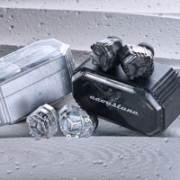
![]() ![]() |
[#5038] 單端胆機同好會 #5037, The schematic shown is the one used in KT66 triode strapped PP. I like the bias arrangement because it can easily adjust the DC balance between the power tubes. Also, the 250 ohm resistor which is common to both KT66 forms a differential circuit. This will further improve the linearity. I used the same circuit but replace the 250 ohm resistor with a MOSFET CCS. Details of the Williamson KT66 PP :- http://www.r-type.org/articles/art-107b.htm Johnny |
johnnykmtang![]() 70.xxx.xxx.22 |
2025-05-03 17:13 | |
|
[#5037] 單端胆機同好會 如果訊號係經VR, 相信就係這種設計。 ![]() |
WilliamsonAudio![]() 182.xxx.xxx.8 |
2025-05-02 13:14 |
[#5036] 單端胆機同好會 Wilson, 佢咁介紹係乜意思? >>The output stage continue to employ ""CCB (constant current bias circuit)"". The music signal is prevented from flowing into the bias adjustment VR 見到佢用咗兩粒黑豆,电流應該好低唔似係EL34 做differential 係 cathode 做CCS ![]() 最後修改時間: 2025-05-02 11:56:18 |
niceday009![]() 182.xxx.xxx.162 |
2025-05-02 11:41 |
[#5035] 單端胆機同好會 Kondo EL34 PP amp, 也應用了新的技術。用constant current source 做 EL34 的bias. CCS 應該是用原子粒。他現在的設計也融入了原子粒, 因為他只用了6072+12BH7膽(這部分只足夠做EL34前面的推動)。 https://www.audionote.co.jp/en/products/power_amplifier/melius.html ""Push-pull circuit further refined from Overture"" The first stage and driver stage are direct coupled, and a new generation pure silver foil capacitors with vibration suppression are used for coupling with the output stage. Moreover, the low impedance design of the whole circuit is aimed the direct sound performance. The output stage continue to employ ""CCB (constant current bias circuit)"". The music signal is prevented from flowing into the bias adjustment VR, enabling pure signal transmission. |
WilliamsonAudio![]() 101.xxx.xxx.131 |
2025-05-02 08:37 |
[#5034] 單端胆機同好會 #5032 那個年代CNC 的機器非常昂貴。所以加工費也會非常之高。 隨著CNC 的普遍性以及廣泛應用。 Kondo 現在的機殼設計也有用到CNC 。 ![]() |
WilliamsonAudio![]() 101.xxx.xxx.131 |
2025-05-02 08:28 |
[#5033] 單端胆機同好會 今天找了出来。分享一下。中間那支膽應該係5687 這張圖嘅資料來源係。當年英國Audio note 賣膽機電路圖紙(好似係10-20英鎊)。給那些DIY 人參考。方便他們賣出更加多的零件。 output膽應該係用211 ![]() |
WilliamsonAudio![]() 182.xxx.xxx.8 |
2025-05-01 23:05 |
[#5032] 單端胆機同好會 日本Audionote出機其實土炮味好重,但這樣形容並非負面,因為有經驗有技術土炮友係做機時永遠放音質第一,例如綫路計算設計,排位及用料等等排第一,外觀或內觀係排第二 最後修改時間: 2025-05-01 22:58:30 |
niceday009![]() 218.xxx.xxx.220 |
2025-05-01 22:42 |
[#5031] 單端胆機同好會 極早期日本 Audio Note. 應該是之前早期MJ雜誌的其中一頁。 ![]() |
WilliamsonAudio![]() 182.xxx.xxx.8 |
2025-05-01 15:58 |
[#5030] 單端胆機同好會 今日執書找到出來。Kondo 除了單端,也有PP 設計的(右手面那一台)。而且更貴 左面是Ongaku SE ![]() |
WilliamsonAudio![]() 182.xxx.xxx.8 |
2025-05-01 15:53 |
[#5029] 單端胆機同好會 A friend got his 2A3 Stereo SE amp built. Here's his words:- Just finished building a 2A3 single-ended amp for my AER open baffle setup, using Johnny’s schematic. Over the years, I’ve tried various amps, but none of them could truly unlock the AER’s potential. Honestly, it got to a point where I lost passion for the hobby — I didn’t even feel like turning on my system anymore. This amp completely changed that. It brought the system to life in a way I didn’t think was possible. Now I can’t stop listening, and I actually don’t want to turn it off. ![]() |
johnnykmtang![]() 70.xxx.xxx.22 |
2025-04-27 17:44 |
[#5028] 單端胆機同好會 原來211,845等牛奶樽胆開機一刹cause stripping, 又知多件事因乜原因,我量度過在845燈絲未熱屏上HV, cathode 條保護fast blow 250mA Fuse可以断,211,845燈絲主要係鎢合金並非表面coating可能唔會有cathode物質脱落問題,但刹那高电流可以整断初級線組 按以下文章描述300B 係冇大問題,試過300B cathode 未熱上HV都唔會將條120mA fast blow 衝断 最後修改時間: 2025-04-06 18:38:40 |
niceday009 ![]() 182.xxx.xxx.214 |
2025-04-06 18:26 |
[#5027] 單端胆機同好會 Good info by WilliamsonAudio....... thank you. The Cary CAD-805RS has a STANDBY/OPERATE switch. This switch is used for turning the 211/845 power tube filament on/off. Then, cathode stripping would be a BIG problem because the 1000V B+ is once the Power switch is ON. Also, the 1KV supply is using diodes for rectification. Johnny |
johnnykmtang![]() 70.xxx.xxx.22 |
2025-04-06 17:35 |
[#5026] 單端胆機同好會 分享 Cathode Stripping 資料。845,211,805,212,833更加需要軟體啟動。 Cathode stripping refers to the physical damage or degradation of a tube's cathode surface due to ion bombardment. In a vacuum tube like a DHT, the cathode is heated directly by a filament to emit electrons. If high voltage is applied between the anode and cathode before the cathode is fully heated, residual gas molecules inside the tube can become ionized. These positively charged ions are attracted to the negatively charged cathode and can strike its surface with enough force to dislodge material from the emissive coating (typically oxides in indirectly heated tubes, but pure or thoriated tungsten in many DHTs).For DHTs, such as the 300B or 2A3, which often use thoriated tungsten filaments, cathode stripping is less of a concern at typical operating voltages (hundreds of volts) compared to high-voltage tubes (e.g., those operating at 10,000 volts or more, like in old radio transmitters). Experts generally agree that in audio applications, the voltages are too low for significant stripping to occur. However, it’s still good practice to allow the filament to warm up before applying full anode voltage to minimize any risk. 最後修改時間: 2025-04-06 08:47:29 |
WilliamsonAudio![]() 182.xxx.xxx.92 |
2025-04-06 08:35 |
[#5025] 單端胆機同好會 #5020 Grid current 重點如下。方便理解。 • This current generates a voltage across the grid leak resistor. • This voltage makes the grid more positive which SUBTRACTS from the bias and results in increase tube current. • This effect is proportional to tube (anode) current and >>so is worse in power tubes<< • This effect also is worse in old “gassy” tubes. • This is why there are always 2 specifications for maximum Rg1 values. One value for cathode (auto) bias where the increased current is opposed by an increased bias due to increased voltage drop across the cathode resistor, and another smaller value for fixed bias where there is no action to oppose the current increase. The mechanism of NEGATIVE grid current, reducing the bias, increasing the current, increasing the negative grid current, reducing the bias etc. etc. round and round, then boom is called thermal run away and is what causes a lot of power tubes to self destruct. 最後修改時間: 2025-04-06 08:25:18 |
WilliamsonAudio![]() 182.xxx.xxx.92 |
2025-04-06 08:25 |
[#5024] 單端胆機同好會 另外我相信用SMPS 燈絲係效果唔錯,如果唔係日本CS PORT 4212 由高压至燈絲都用上SMPS,可能仲好過Rod Coleman Gyrator,不過SMPS lifespan可能冇linear PS咁耐用,特別係用IRON Choke PS 我認為胆係硬淨過原子粒好多好多,原子粒电压或电流過荷或靜电問題一瞬就釘蓋,300B就算你冇做高压延遲好多都冇事(唔知有冇99.999%),就算211,845本身都冇事但輸出牛初級就唔敢包 最後修改時間: 2025-04-05 22:00:17 |
niceday009![]() 182.xxx.xxx.214 |
2025-04-05 21:40 |
[#5023] 單端胆機同好會 图,左及右300B燈絲焊接時正負对調 ![]() 最後修改時間: 2025-04-05 21:28:51 |
niceday009![]() 182.xxx.xxx.214 |
2025-04-05 21:26 |
[#5022] 單端胆機同好會 最近出外,依家睇返DHT燈絲分析 用過AC及DC點300B, Hum AC 約4.4mV, DC non regulated hum 0.8mV, 但沒有感覺AC會靚声咗,相信前人推介AC係耐用方面,要对300B燈絲正負对換去做成耐用,我盡量唔加額外SS線路,我方式係左右300B燈絲正負焊時不一樣,用家只須每兩三個月互換300B就燈絲正負反轉,唔使焊過,當作保養事項,唔記得都冇事,反正正負不立刻对換也不會短時間有任何事 211, 845必須做高壓延遲45秒,211,845 燈絲未熱時浪湧可以令瞬間电流高過250mA, 最嚴重可以衝斷輸出牛初級,300B燈絲未熱就唔會咁嚴重,好多外國市面300B機都沒做高壓延遲 最後修改時間: 2025-04-05 21:33:04 |
niceday009![]() 182.xxx.xxx.214 |
2025-04-05 21:16 |
[#5021] 單端胆機同好會 Regarding the 300B grid current, my understanding is that:- The grid current will appears when the signal is very large that portion of the signal gets to the positive potential. With this positive voltage appears at the grid, there will be small amount of current from the grid. The current will be stored at the coupling capacitor which lower the grid-cathode potential. Then, the bias voltage will be changed. The electric charged to the capacitor will be dissipated through the grid resistor (say 100~250K). This is the reason why there is a limit of the grid resistor maximum value to avoid such issue. Using the Inter-stage transformer or Grid Choke would prevent such instability because the inductor would have very low DC resistance and won't store the grid current at all. 最後修改時間: 2025-04-05 19:25:47 |
johnnykmtang![]() 70.xxx.xxx.22 |
2025-04-05 19:17 |
[#5020] 單端胆機同好會 grid current 有點複雜。可以參考下面。比較長,要花時間才能看完。 https://www.diyaudio.com/community/threads/amplifiers-that-exceed-grid-leak-resistance.261130/ There are 3 types of grid current Current flowing into the grid is known as POSITIVE grid current • When the cathode is heated a cloud of electrons forms around the cathode known as a “space charge” • Some of these electrons gather at the grid. These electrons then flow out of the grid which is the same as saying that current flows into the grid. • This positive grid current generates a voltage across the grid leak resistor (Rg1) • This voltage makes the grid more negative which ADDS to the bias • If the grid leak resistor is large enough then this positive grid current can generate the entire required bias – This is known as “Grid Leak Bias” POSITIVE grid current is a low level phenomenon and can easily be overshadowed by NEGATIVE grid current Current flowing out of the grid is known as NEGATIVE (or REVERSE) grid current • Negative grid current can be caused by 1. gas ioniszation current 2. leakage current (grid to cathode) 3. grid emission (from grid being heated by the cathode, screen or anode) • gas ionization current dominates with the other 2 being low level effects • As electrons accelerate “up” the tube from cathode toward the anode, some of them collide with residual gas atoms. This collision is energetic enough that it strips an outer orbit electron from the gas atom which turns it into a positively charged ion. • The positively charge ion accelerates back “down” the tube toward the cathode • Some of these positively charged ions collect at the grid (which is usually the most negative potential of any tube element). Electrons must flow into the grid to neutralize these ions which is the same as saying that current must flow out if the grid • This current generates a voltage across the grid leak resistor. • This voltage makes the grid more positive which SUBTRACTS from the bias and results in increase tube current. • This effect is proportional to tube (anode) current and so is worse in power tubes • This effect also is worse in old “gassy” tubes. • This is why there are always 2 specifications for maximum Rg1 values. One value for cathode (auto) bias where the increased current is opposed by an increased bias due to increased voltage drop across the cathode resistor, and another smaller value for fixed bias where there is no action to oppose the current increase. The mechanism of NEGATIVE grid current, reducing the bias, increasing the current, increasing the negative grid current, reducing the bias etc. etc. round and round, then boom is called thermal run away and is what causes a lot of power tubes to self destruct. This is made worse by the fact that Rg1 values in most guitar amps ignore the recommended maximum Rg1 values. This is done so as to not load down the output of the phase splitter too much. This is usually compensated to some degree by biasing the output tubes at 70% of rated maximum dissipation, that is, reduce the tube idle current by 30%. That allows use of an Rg1 value of about double the recommended maximum which is based upon running the tube at 100% of its dissipation rating. This helps at idle but does not help much when running the amp with full signal. So NEGATIVE or REVERSE grid current is something you really need to watch in power tubes. It can be a problem in small signal tubes as well, particularly high mu triodes which led to the RDH "Rule of Thumb" that for high mu triodes (like 12AX7, 6SL7 etc.) that Rg1 should be no more than 3 times the anode load resistor for cathode bias and no more than twice the anode load resistor for fixed bias. Those familiar with 12AX7 circuits used in guitar amps will note that Rg1 is often ten times the anode load resistor value. This is because one of the defining characteristics of a 12AX7 which actually makes it ideal in guitar amps is unusually low NEGATIVE grid current. The above also explains why grid leak bias does not work with older gassy tubes. The negative grid current from the gas ionization opposes the positive grid current needed to establish the grid leak bias. Grid current is statistical in nature, that is to say that as well as developing a DC voltage across Rg1 it also develops a noise (hiss) voltage across Rg1 which is then amplified by the tube. Low Rg1 values not only give you a more stable bias point but also lower noise. You can think of this as the lower Rg1 shunting the grid noise to ground. There is one more type of grid current, GRID RECTIFICATION Current. When the grid is taken positive with respect to the cathode the grid to cathode circuit starts to look like a forward biased diode. Current into the grid increases with more positive voltage and usually this has the effect of clamping the positive going signal at the grid. The current also charges up any interstage coupling (DC Blocking) capacitor and this is the root cause of blocking distortion. Cheers, Ian |
WilliamsonAudio![]() 182.xxx.xxx.92 |
2025-04-05 19:12 |
[#5019] 單端胆機同好會 extracted from #5015 by EM Labs "..........please keep well in mind, that the grid current creates a voltage across the grid resistor. This is a DC current, coming "from" the grid. So, the polarity of this voltage will off-bias the tube such that plate current will increase, above the intended value. In some bad cases, leading to thermal destruction of the tube. ......" 1) ".....a DC current, coming "from" the grid......" It's actually electrons, not current 2) ".....the polarity of this voltage will off-bias the tube such that plate current will increase, above the intended value...." Grid leak electrons actually flow this way, Cathode -> Grid -> Grid Leak Resistor -> Cathode Bias Resistor -> Cathode. Current flows in opposite direction. Electrons flow from low voltage potential to high potential. (e.g. from signal ground 0V to cathode, approx. +70V for 300B in self-bias configuration) While Current flows from high voltage potential to low potential (e.g. from anode to cathode) As electron flows from grid to ground via grid leak resistor, yes, a dc voltage develops across the resistor, but in an opposite direction. The resistor lead that connects to grid should be more negative, compared to the other end. As a result, grid dc potential should be more negative and the tube should be more negatively biased. Plate current should drop instead. I am afraid this theory alone does not explain why a tube can malfunction due to grid leak current (or electrons). correct me if i am wrong. |
bambino![]() 210.xxx.xxx.231 |
2025-04-05 11:40 |